
SHACKLESS & CLEVIS
About The Product
Shackles and clevises are mechanical connectors used to join various components of electrical transmission systems, particularly in overhead lines and substation assemblies. They provide strong, flexible, and secure links between conductors, insulators, and structures.
Shackles are U-shaped or bow-shaped connectors secured with a pin or bolt across the opening.
Clevises are U-shaped fittings with a pin through the ends, designed to connect other hardware (like eye bolts, insulators, etc.).
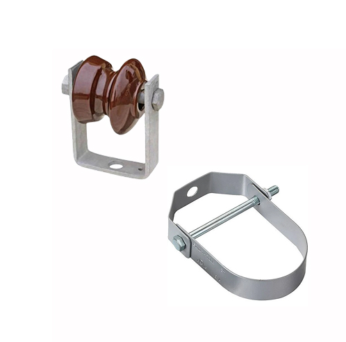
featueres
1. Material Usually forged steel or malleable iron, hot-dip galvanized for corrosion resistance.
2. Design High mechanical strength and durability under tension and mechanical load.
3. Corrosion Resistance Zinc-coating (galvanization) ensures long service life in outdoor environments.
4 Interchangeability Designed to be compatible with standard-sized fittings and hardware.
5. Ease of Assembly: Bolted or pinned connections make them easy to install and remove.
usage
1. Overhead Power Lines – Connect conductors, insulators, suspension clamps.
2. Substations – Secure and link bus bars, jumpers, and insulators.
3. Guy Wire Assemblies – Provide anchoring and flexibility in guy wire configurations.
4.Pole Hardware – Interface with brackets, thimbles, and other pole line accessories.
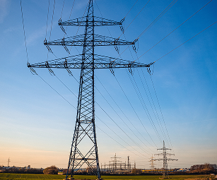
size and range
standardization
1. IEC (International Electrotechnical Commission)
2. ANSI C135 (American National Standards for line hardware)
3. BS (British Standards)
4. IS 2486 / IS 2074 (Indian Standards for overhead transmission fittings)
5. ASTM A153 (for hot-dip galvanizing)
aPPLICATION
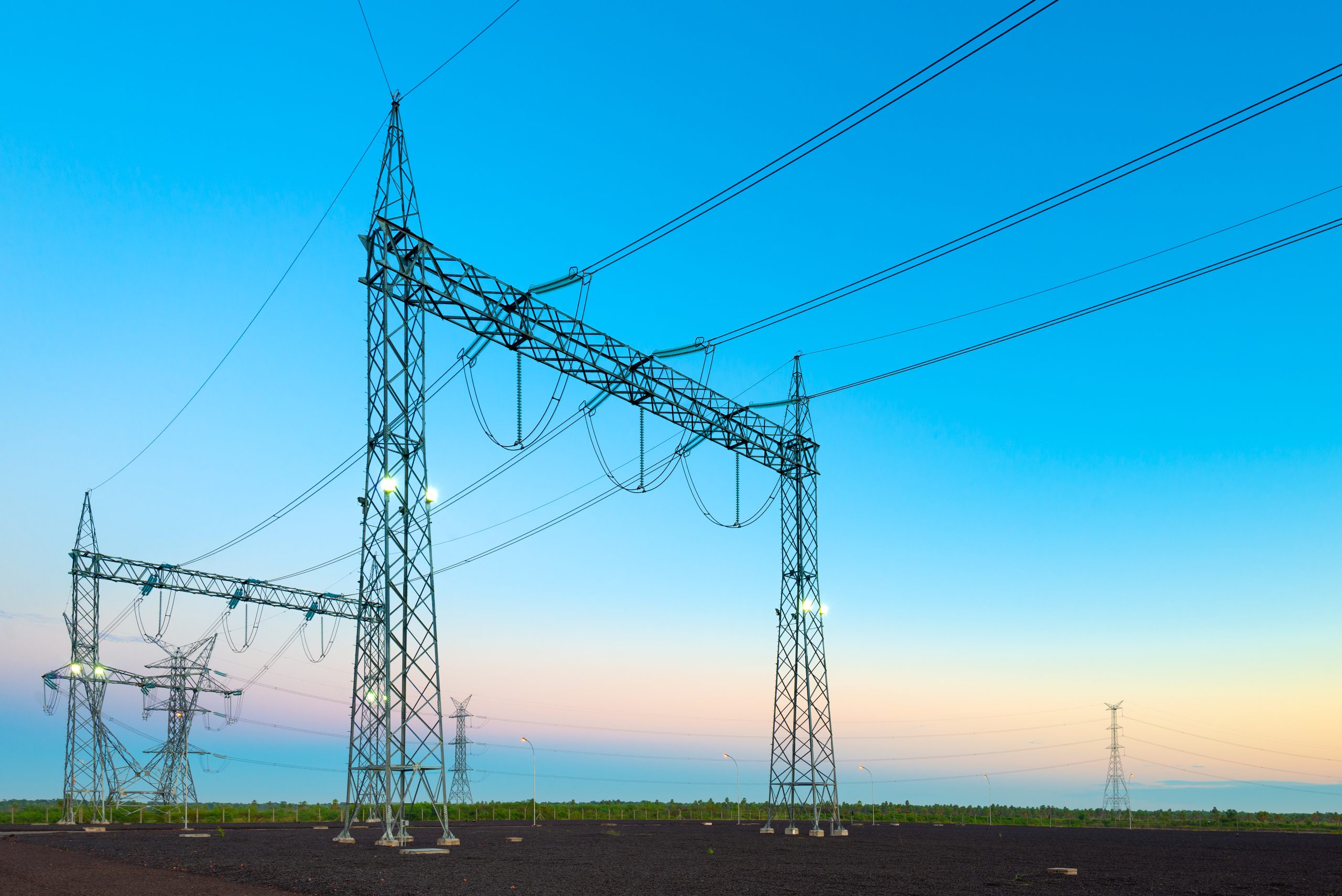
1. Transmission lines (132kV to 765kV)
2. Distribution networks (11kV to 66kV)
4. Wind and solar power systems
5. Railway electrification systems
INSTALLATION
1. Verify component compatibility (matching pin size, hole size, material).
2. Insert clevis or shackle bolt through aligned holes.
3. Tighten nuts or secure pins using locking cotter pins or nuts.
4. Ensure mechanical alignment and that no side loading occurs.
5. Check for free movement (especially in tension joints).