
INSULATOR PIN
About The Product
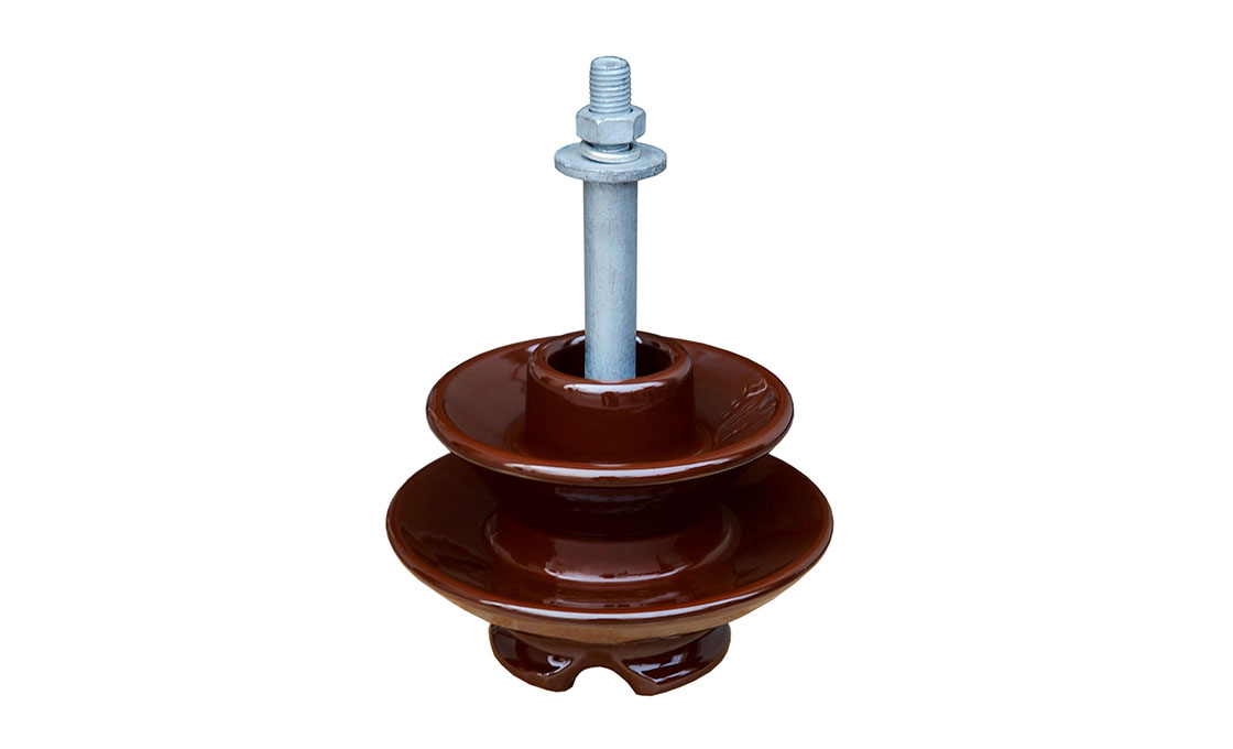
An Insulator Pin is a critical component in electrical distribution systems. It is used to securely support pin-type insulators on cross arms or pole tops of overhead power lines. These pins are essential for maintaining the electrical insulation between the energized conductor and the grounded supporting structure.
featueres
1. High Mechanical Strength: Made from forged steel, ductile iron, or malleable cast iron, offering resistance to mechanical stress.
2. Corrosion Resistance: Often galvanized (hot-dip zinc-coated) to resist environmental effects.
3. Standardized Threads: Designed to fit standard pin-type insulators (ANSI or BS thread).
4. Secure Mounting: Equipped with nuts and washers for firm attachment to crossarms or poles.
5. Durability: Engineered to withstand mechanical loads, temperature variations, and long-term exposure to the elements.
usage
1. Support pin-type insulators, which hold the electrical conductors.
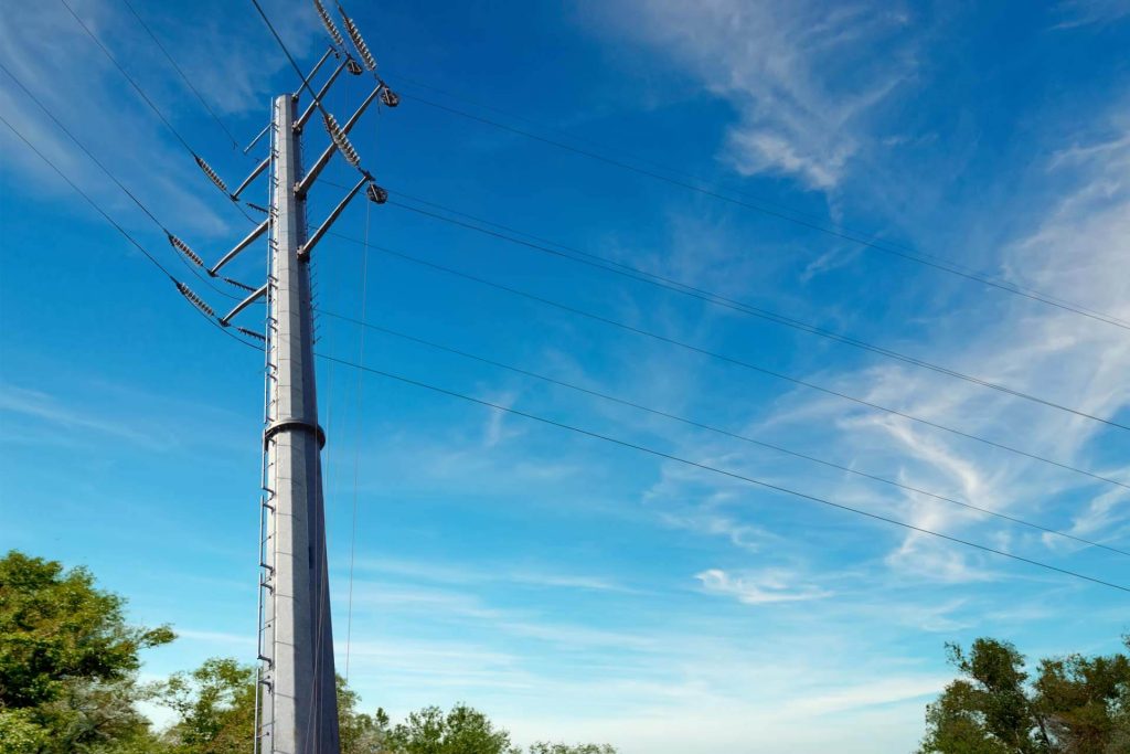
2. Maintain safe electrical clearance and mechanical stability on overhead transmission and distribution lines.
3. Help isolate the conductor from the pole/tower to prevent electrical faults.
size and range
standardization
1. ANSI C29.5 / C29.6 – For insulator pins in North America
2. BS 3288 / BS EN 50483 – British/European Standards
3. IS 2486 (India) – Part 1: Insulator fittings;
Part 2: Pins for overhead lines
4. IEC 60383 – International standard for insulators used in overhead lines
aPPLICATION
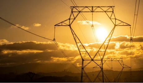
1. Power Distribution Lines: Especially in 11 kV to 33 kV systems.
2. Rural and Urban Electrical Networks
3. Railway Electrification
4. Street Lighting and Public Utility Lines
5. Industrial Overhead Distribution Systems
INSTALLATION
1. Select proper pin size according to line voltage and insulator type.
2. Fix the pin on the pole top or crossarm using bolts, clamps, or direct driving.
3. Tighten using nuts and washers if applicable.
4. Screw the pin-type insulator onto the threaded top of the pin.
5. Ensure alignment with the conductor and proper mechanical load distribution.
6. Check torque and locking to prevent loosening due to vibration or wind.